February 16, 2026. 4:30 PM.
Log 5 - Blinking LED
Let's start with the basics - an LED blinker for a dev board with a built-in LED.
This is equivalent to the following code on Arduino:
void setup() {
    pinMode(LED_BUILTIN, OUTPUT);
}
void loop() {
    digitalWrite(LED_BUILTIN, HIGH);
    delay(1000);
    digitalWrite(LED_BUILTIN, LOW);
    delay(1000);
}
There would also be a reset state that's needed, that classical Arduino coding doesn't support.
There are a few things to do here:
- Write SystemVerilog code equivalent to the Arduino code above.
- Figure out where the LED and clock are on the FPGA board.
- Update the assignment editor with those pins.
- Compile the SV file and bug-test it until it compiles
- Flash the compiled bitstream to the FPGA board
- Fix the code until it blinks the LED on the FPGA board
SystemVerilog Code
Here's the SystemVerilog code I wrote for this, with all the documentation for each part of the code:
// LED Blinking module

module blinkLED ( //define signals for blinkLED (Inputs & Outputs)
    input  logic clk,		// clock input
    input  logic rst_n,    // active LO reset input
    output logic led			// LED output
);

// 50 MHz clock speed -> 25,000,000 cycles = 0.5 sec blink rate
localparam int MAX_COUNT = 25_000_000;

// Create a logic vector called 'counter'
// the width is equal to the ceiling of log base 2 of N-1
// which is the way of determining the number of bits to store MAX_COUNT
logic [$clog2(MAX_COUNT)-1:0] counter;

// Create a flip-flop that updates on the rising edge of CLK or falling edge of RST_N
always_ff @(posedge clk or negedge rst_n) begin
    // if reset is LO, reset the state
    if (!rst_n) begin
        counter <= 0;
        led     <= 0;
    end
    // else, (reset is HI), run normal operation
    else begin
        // If the counter reaches the max state, then
        if (counter == MAX_COUNT - 1) begin
            counter <= 0;			 // reset counter, and
            led     <= ~led;      // toggle LED
        end
        // If the counter has not reached the max state, increment it
        else begin
            counter <= counter + 1;
        end
    end
end
endmodule // end of blinkLED module
Pins
Luckily, the FPGA dev board I bought had all the relevent pins labelled on the silkscreen. I found the LED, CLK, and BTN pins, and updated the pin assignments. The board has 5 LEDs on pins 1,2,3,7, and 11. The 50Mhz clock is on pins 24 & 25, and the 4 buttons on this board are on pins 73, 80, 89, and 114.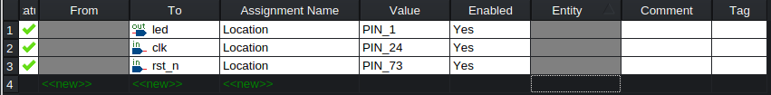
Compilation
I had to add the SystemVerilog file to the project, and then compile it. Ctrl+L to build the project, and fix the few errors that came up.Programming
Now, I just program the FPGA. The device could be found under Tools -> Programmer. From there, I pressed "Auto-Detect" and it found my FPGA board, where I had to select the correct board type: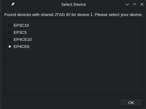
Selecting my board, I then had to select the .sof file that was generated from the compilation step, and then hit "Start" to program the FPGA.